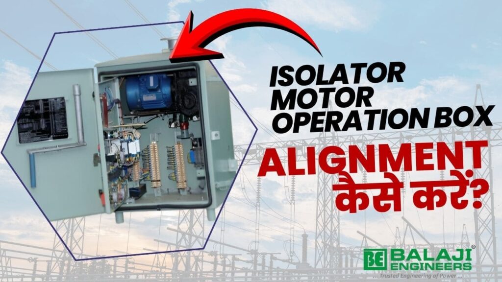
How to Align Isolator Motor Operation Box with Isolator ?
Proper alignment of the Isolator Motor Operation Box (MOB Panel) IEC 62271-102: High-voltage switchgear and controlgear – Alternating current disconnectors and earthing switches.with the isolator is a critical step in substation installation.
Incorrect alignment can lead to:
- Improper opening/closing of isolator
- Mechanical stress on shaft & gearbox
- Failure of limit switches
- Reduced equipment life
This guide explains the step-by-step procedure for isolator alignment, ensuring smooth and reliable operation in 33kV, 66kV, 132kV,220 KV and higher voltage substations.
What is Isolator MOB Panel Alignment?
Isolator alignment refers to the correct positioning of the motor-operated mechanism (MOM / MOB Panel) with respect to the isolator operating shaft.
The goal is to ensure:
- Smooth torque transmission
- No mechanical binding
- Accurate open/close position
- Operation in remote as well as operation in mechanical type.
Tools Required for Alignment
- Spirit level
- Measuring tape
- Spanner & torque wrench
- Alignment rod / straight edge
- Feeler gauge
- Marker / chalk
Step-by-Step Alignment Procedure
1.Foundation & Mounting Check
- Ensure the control box mounting structure is rigid and level
- Check base frame alignment with isolator structure
- Tighten foundation bolts properly
- Make sure that operation pipe is perpendicular to BOX
- Accurate box fixing structure will keep operation smooth
- Align the MOB output shaft clamp with isolator input shaft (Connecting clamp )
- Both shafts must be:
- In same horizontal axis
- Free from angular misalignment
- Improper alignment may put in trouble for operation
3.Coupling Adjustment (Most Critical Step)
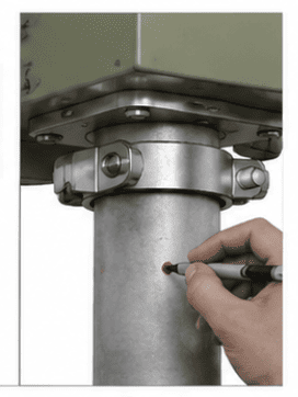
- Take a size from Isolator to Motor operation box top flange
Once the measurement from the Isolator to the MOB top flange is verified (typically 2.0 to 2.5 meters), rest the pipe on the top flange and mark it precisely through the holes of the MOB top holding clamp.
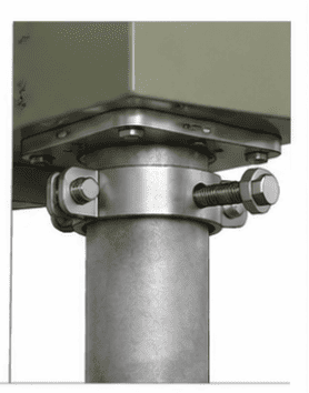
- Install coupling between MOB and isolator shaft
- Maintain proper gap as per design (usually 2–5 mm)
- Ensure:
No tight fit
No excessive looseness
4.Manual Operation Check
- First of all tight lightly upper side and bottom side of operation pipe .
- Try to rotate operation pipe with help of mechanical handle given in Motor operation box .
- Operate isolator manually
- Check:
Smooth rotation
No jerks or obstruction
Equal movement in both directions
If feels jerks , tight the top and bottom of pipe with doing proper setting .
Once the pipe is get aligned with top clamp of isolator and bottom clamp of operation box . Than move for next step
Once the mechanical handle rotates properly and Moving contact is moving properly and fit properly in fixed contact than you have completed the mechanical setting of Isolator .
- After successful rotation of mechanical movement of moving contact in the fixed contact you may go for electrical setting isolator .
Direct electrical setting may create problem to Isolator if mechanical operation test is skipped .
5. Limit Switch Setting
- Once you have confirmed that the Isolator Moving contact is moving properly and setting properly in fixed contact this gives you permission to go for electrical operation and setting
- Pro tip – 1St Mechanical Test then Electrical setting .
- Set OPEN and CLOSE limit switches correctly
- Ensure:
Motor stops at exact position
No over-travel
- Limit Switch – Are sensitive and need to position on proper place because the overall rotation of moving contact is restricted by limit switch . Good quality limit switches are to be used in Motor operation box to insure the proper operation of Moving contact of Isolator .
WATCH VIDEO
- Isolator Motor Operation Box India
- Isolator Control Box Manufacturer in India
- MOB Panel for Isolator India
- Motorized Isolator Control Panel India
- Substation Isolator Control Box Supplier India
- 33kV / 66kV / 132kV Isolator Control Box India
- High Voltage Isolator Control Cabinet
- Electrical Isolator Panel Manufacturer India
- Motor Operated Isolator Control Panel
- Isolator Drive Mechanism Control Box
- Motorized Disconnect Switch Control Box
- Substation Isolator Control Panel
- Outdoor Isolator Operating Mechanism Box
6. Electrical Connection & Trial
- Connect control supply (110V / 220V DC)
- Perform trial operation:
Local mode
Remote mode
- Check:
Direction of rotation
Indication lamps
Auxiliary contacts
PRO TIP – Insure all wiring is done as per SLD given by Isolator manufacturer . Use proper wiring from CRP (Control relay panel to Isolator motor operation box ) .
- Tighten all bolts after alignment
- Check complete system again
- Ensure weatherproof sealing of panel
- Check earthing properly fixed in the ground
- Insure nothing like spanner or other apparatus left in the motor operation panel
- Make sure your Control volage and Power voltage is selected properly .
- Confirm the all switchgear used in Motor operation box is as per your Control volage and Power voltage
Common Alignment Mistakes to Avoid
- Misalignment of shaft (major failure reason)
- Improper coupling gap
- Skipping manual operation test
- Wrong limit switch setting
- Loose mounting structure
Best Practices for Long Life
- Always use precision alignment tools
- Perform alignment in no-load condition
- Recheck after first 5–10 operations
- Apply lubrication where required
- Follow utility standards (PGCIL / GETCO / MSETCL etc.)
Applications
- Power Transmission Substations
- Switchyard Installations
- Solar & Wind Projects
- Industrial Power Distribution
Conclusion
Correct alignment of the Isolator Motor Operation Box (MOB Panel) is essential for:
- Smooth operation
- Longer equipment life
- Reduced maintenance
- Reliable substation performance
Following the above procedure ensures error-free installation and long-term reliability of your isolator
Frequently Asked Questions (FAQs) on Isolator Motor Operation Box Alignment
What is an Isolator Motor Operation Box (MOB Panel)?
Why is alignment of the isolator motor operation box important?
What happens if isolator alignment is incorrect?
How do you align an isolator motor operation box with an isolator?
What is the correct gap for isolator shaft coupling?
Why is manual operation important before electrical testing?
What are common mistakes during isolator MOB panel installation?
Where are isolator motor operation boxes used?
Who are the leading isolator motor operation box manufacturers in India?
India has several reputed manufacturers supplying isolator motor operation boxes, control panels, and mechanism boxes for domestic utilities and export markets, meeting international standards and specifications. Company named Balaji Engineers Isolators Private limited . with brand name Balaji Engineers is trusted brand in manufacturing of Isolator Operation gear drive boxes in India , Exporting from India to Africa ,Asian countries and Europe.
TALK WITH ISOLATOR EXPERT
- How to adjust limit switch in substation isolator MOB
- Isolator motorized mechanism troubleshooting
- Double break isolator mechanical alignment procedure
- Disconnect switch motor operating mechanism installation manual
- Substation isolator torque settings and coupling gap
- Balaji Engineers isolator drive mechanism drawing
“When sourcing equipment, choosing a reliable Isolator Motor Operation Box Manufacturer in India is key. Trusted brands like Balaji Engineers supply robust outdoor motorized mechanism control panels designed to handle the rigorous demands of 33kV to 132kV and 220kV substation environments.”