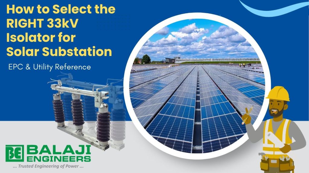
Selecting the right 33kV isolator for a solar substation is a critical engineering decision. A wrong selection can lead to overheating, flashover, frequent maintenance, or even complete shutdown of the solar plant. This guide explains the key technical parameters, standards, and practical site considerations engineers should evaluate before finalizing a 33kV isolator.
What is a 33kV Isolator Used for in a Solar Substation?
A 33kV isolator (disconnector) is a mechanical switching device used to isolate electrical equipment during maintenance. In solar substations, isolators are typically installed:
Poor alignment can lead to:
- On 33kV feeder lines
- Between inverter transformer and switchyard
- Near circuit breakers for visible isolation
- Important: Isolators are operated only under no-load conditions.
Key Technical Parameters for Selecting a 33kV Isolator
1. Rated Voltage and System Voltage
| Parameter | Requirement |
|---|---|
| Nominal System Voltage | 33 kV |
| Highest System Voltage | 36 kV |

2. Rated Current
The rated current depends on feeder capacity and future expansion.
| Common Ratings | Application |
|---|---|
| 400 A | Small to medium solar plants |
| 630 A | Standard utility requirement |
| 800 A | High-capacity feeders |
| 1250 A | |
| 1600 A |
- Tip: Many utilities prefer 630A for margin and standardization.
3. Creepage Distance (Very Critical for Solar Projects)
Solar substations are often located in:
- List Item #1
- List Item #2
- List Item #3
| Pollution Level | Recommended Creepage Distance |
|---|---|
| Medium | ≥ 25 mm/kV |
| Heavy | ≥ 31 mm/kV |
For most Indian solar projects, 31 mm/kV creepage distance with polymer insulators is strongly recommended.
4. Insulator Type: Polymer vs Porcelain
| Parameter | Polymer Insulator | Porcelain Insulator |
|---|---|---|
| Weight | Light | Heavy |
| Pollution Performance | Excellent | Moderate |
| Maintenance | Low | Higher |
| Breakage Risk | Very Low | Higher |
- Preferred Choice for Solar: Polymer insulators
5. Type of Isolator Mechanism
Common isolator types used in 33kV solar substations:
- Vertical Break Isolator – Most commonly used
- Centre Break Isolator – Used in Distribution and Transmission Substation .
- Double break isolators are preferred due to compact design and easy maintenance.
6. Earthing Switch Requirement
| Configuration | Recommendation |
|---|---|
| With Earthing Switch | For grid & utility substations |
| Without Earthing Switch | EPC-defined solar projects |
Confirm whether:
- Earthing switch is required
- Manual or motorized operation is needed
7. Manual or Motorized Operation
| Operation Type | Usage |
|---|---|
| Manual | Small substations |
| Motorized | SCADA-controlled solar plants |
Motorized isolators must comply with:
- Remote operation requirements
- Local/remote selector switch
- Interlocking logic
Applicable Standards for 33kV Isolators
Ensure compliance with the following:
- IEC 62271-102 – High-voltage disconnectors
- IS 9921 – Indian standard for isolators
- Utility-specific technical specifications
Environmental & Site Conditions to Check
Before final selection, verify:
- Ambient temperature (up to 50°C)
- Wind speed
- Seismic zone
- Altitude (above 1000 m requires correction)
- Corrosion risk (coastal / industrial area)
Common Mistakes to Avoid
- Selecting minimum creepage distance
- Wind speed
- Seismic zone
- Altitude (above 1000 m requires correction)
- Corrosion risk (coastal / industrial area)
Typical 33kV Isolator Technical Specification Summary
| Parameter | Typical Value |
|---|---|
| Rated Voltage | 36 kV |
| Rated Current | 400A / 630A / 800A /1250 A / 1600 A |
| Insulator | Polymer |
| Creepage Distance | 31 mm/kV |
| Standard | IEC 62271-102 |
| Operation | Manual / Motorized |
Final Recommendation
Based on field experience in Indian solar substations, the recommended configuration delivers high reliability with minimal maintenance over the plant life.
For most Indian solar substations, the ideal selection is:
- 33kV, 36kV class isolator
- Polymer insulator with 31 mm/kV creepage distance
- 630A rated current
- IEC 62271-102 compliant design
Frequently Asked Questions
Q1. What creepage distance is best for 33kV isolators in solar projects?
For most Indian solar projects located in dusty or high-pollution areas, 31 mm/kV creepage distance using polymer insulators is recommended.
Q2. Is 400A sufficient for a 33kV solar feeder?
400A may be sufficient for small plants, but 800A is preferred to accommodate future expansion and reduce thermal stress.
Q3. Are polymer insulators reliable for outdoor solar substations?
Yes. Polymer insulators offer superior pollution performance, lower weight, and reduced maintenance compared to porcelain.
Q4. Is earthing switch mandatory with 33kV isolators?
It depends on utility and EPC requirements. Grid-connected substations typically require an earthing switch, while some EPC solar projects may not.
Q5. Which standard should a 33kV isolator comply with?
The isolator should comply with IEC 62271-102 and applicable IS standards, along with utility-specific technical specifications.
People Also Search For
- What is an isolator in a substation?
- Isolator vs circuit breaker – what is the difference?
- 33kV isolator specification for solar substation
- 33kV isolator GTP parameters
- What is the creepage distance requirement for 33kV isolator?
- Polymer vs porcelain insulator – which is better for solar projects?
- Types of isolators used in substations
- 33kV isolator with earthing switch vs without earthing switch
- Vertical break isolator vs centre break isolator
- Best isolator for solar power plant substations
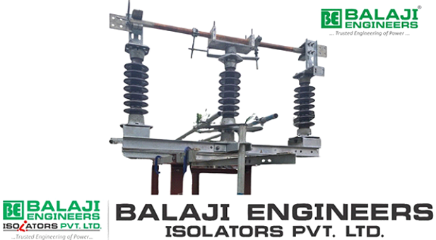
About the Manufacturer
Balaji Engineers Isolators Private Limited manufactures isolator disconnectors for solar, wind, and grid substations, designed to meet Indian utility and EPC requirements. Products are engineered for high pollution zones, harsh outdoor conditions, and long service life.